Cleaner Robot — Why I Built It This Way
Every major design decision, the alternatives I rejected, and the technical reasoning behind each choice.
What I Built and Why
A custom robot vacuum and mop designed from scratch — including all electronics, navigation, and mechanical systems.
Project summary and design philosophy
Internal R&D prototype — built to learn and to fix what the market hasn't solved
What I'm Building
A fully custom robot vacuum and mop with 4 custom PCBs, a 3D-printed chassis, laser navigation, and dual cliff-sensor fusion. Every subsystem — power management, motor control, navigation, sensing — is designed from scratch rather than purchased as a black box.
Why Not Just Buy One?
Commercial robots solve 80% of the problem. The remaining 20% — dark floor false positives, hair tangling, mid-clean navigation failures — is what I'm targeting. Building from scratch lets me fix these at the design level, not paper over them in software.
Scope for v1
- Round body, 340mm diameter, differential drive
- LiDAR + IMU + floor camera navigation (ROS2 + Cartographer SLAM)
- 10,000 Pa suction with spiral-fin anti-tangle brushroll
- Passive gravity-fed mop with servo lift (no auto-wash)
- Single USB-C EPR port for charging and debug
- No docking station — manual pad replacement
- 4 custom PCBs manufactured by JLCPCB
Key Numbers
How to Read This Document
Each section covers one design decision: what I chose, what I rejected, and the technical reason. Decisions are grouped by subsystem. Click any header to expand or collapse the detail. Use the sidebar to jump to a specific topic.
Two-Brain Architecture
Why the robot has two separate computers instead of one.
Split navigation and motor control across two processors
Raspberry Pi 5 (navigation) + STM32F405 (real-time control)

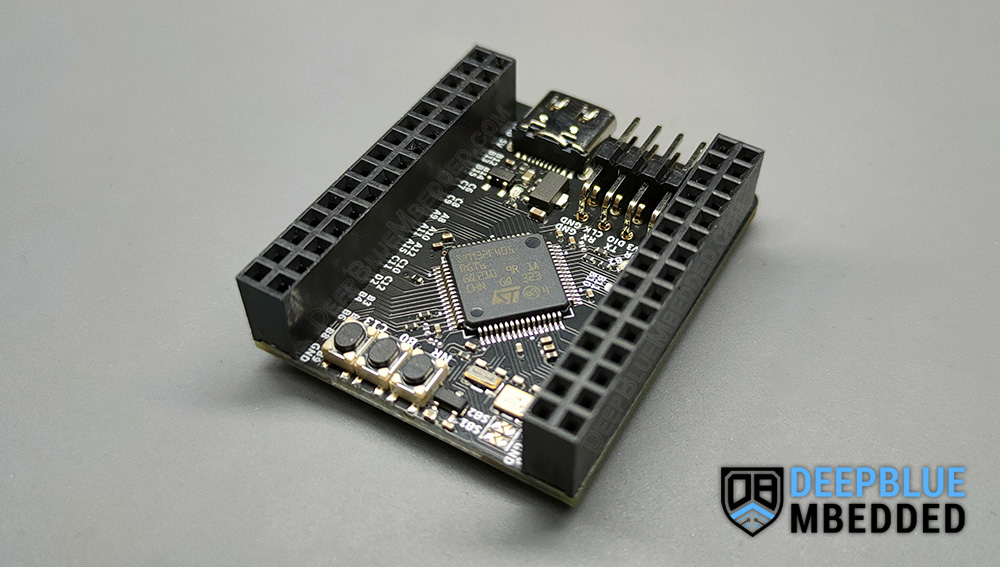
The Core Problem
Navigation and motor control have fundamentally incompatible requirements. Navigation is computationally heavy but timing-tolerant — it's fine if it takes 50ms to calculate the next path. Motor control is computationally light but requires microsecond-precise timing — a 10ms delay in the motor feedback loop causes wheel speed oscillation and unstable movement.
- Linux OS scheduler introduces timing jitter
- SLAM + camera AI steals CPU from motor loops
- Motor instability when navigation workload spikes
- RPi runs Linux freely — navigation has full CPU
- STM32 runs FreeRTOS — guaranteed microsecond timing
- Each processor does exactly one job, perfectly
How They Communicate
// RPi sends high-level commands over UART at 115200 baud
RPi:   "MOVE_FORWARD speed=0.3"  // once per ~33ms (30Hz)
STM32: reads command, runs PID loop 1000× per second
       adjusts left/right PWM duty cycle to maintain target speed
Analogy
Think of it like an aircraft: the autopilot (RPi) decides heading and altitude; the flight control computer (STM32) makes thousands of tiny adjustments per second to actually hold that heading. Both are necessary. Neither can do the other's job well.
Raspberry Pi 5 (4GB)
Why this specific model and not an older or smaller Pi.
Raspberry Pi 5 — 4GB RAM variant
Over RPi 4B, RPi Zero 2W, and RPi CM4
Why Not RPi Zero 2W?
Only 512MB RAM. SLAM algorithms (specifically Cartographer) require 500MB+ at runtime — the Zero 2W would spend all its time swapping to SD card and the navigation would be unusably slow.
Why Not RPi 4B?
Viable, but the RPi 5's PCIe slot is the deciding factor. It allows attaching a Hailo-8L AI accelerator (13 TOPS) for floor classification inference — important when I add more sophisticated carpet/mess detection in later versions. The RPi 5 also has two CSI camera ports vs the 4B's one, giving us a spare camera interface.
Why Not RPi CM4?
The Compute Module 4 has no on-board ports — you design a custom carrier board. That's the right choice for a production product but adds a fifth PCB to design for this prototype. Deferred to v2.
Power Consideration
The RPi 5 draws 5–12W under load — more than the RPi 4B's 3–7W. I account for this in the battery budget. At full system load (~20W total), my 3S2P 5200mAh pack provides approximately 60–75 minutes runtime.
STM32F405RGT6
Why this specific microcontroller for real-time motor control.
STM32F405RGT6 — 168MHz ARM Cortex-M4
Running FreeRTOS with dedicated tasks per subsystem
Peripheral Requirements
I counted every hardware interface the MCU needs to drive:
Required peripherals:
  1× UART    → RPi communication
  1× SPI     → LiDAR (high data rate)
  1× I²C     → IMU + cliff ToF sensors (shared bus)
  5× PWM     → 4 motor drivers + 1 mop lift servo
  2× GPIO    → bumper switches (interrupt-driven)
  1× USB     → debug + firmware flashing

STM32F405 provides:
  6× UART, 3× SPI, 3× I²C, 12× PWM timers, USB OTG FS
  → Sufficient with headroom for future additions
Why Not ESP32?
The ESP32 is popular for hobbyist robotics but its dual-core architecture shares resources unpredictably. At 240MHz it's fast, but FreeRTOS on ESP32 has known timer jitter issues that cause motor speed fluctuation. The STM32F4 family has 15+ years of industrial motor control use — well-characterized, deterministic behavior.
Why Not Arduino?
Arduino's ATmega328 runs at 16MHz with no hardware FPU. Running PID loops for 4 motors + sensor polling at 1kHz would consume 100% CPU with no headroom. The STM32F405 has a hardware floating-point unit — PID math runs in single-cycle instructions.
ROS2 + Nav2 + Cartographer SLAM
Why I use the industry-standard robotics software stack.
ROS2 with Nav2 navigation and Cartographer SLAM
Over custom Python SLAM implementation
What Each Component Does
- ROS2 — Robot Operating System. A message-passing framework connecting sensors, algorithms, and actuators. Each component publishes/subscribes to topics (like an event bus).
- Cartographer — Google's SLAM library. Fuses LiDAR + IMU data to build a 2D map and track the robot's position within it simultaneously.
- Nav2 — Navigation stack. Takes the Cartographer map and plans collision-free paths to cleaning waypoints. Handles recovery behaviours (stuck detection, backout manoeuvres).
- 6–12 months to write a working SLAM algorithm
- Would reinvent decades of solved research
- No community support when bugs appear
- SLAM works on day one — focus on robot-specific code
- Industry standard — same stack used in commercial robots
- Massive community, extensive documentation
Learning Curve Acknowledgement
ROS2 has a steep initial learning curve — approximately 2–4 weeks to become productive. This is accepted because the alternative (writing SLAM from scratch) would take months and produce an inferior result.
LiDAR — YDLIDAR T-mini Plus
Why this sensor over alternatives, and why LiDAR over camera-only navigation.
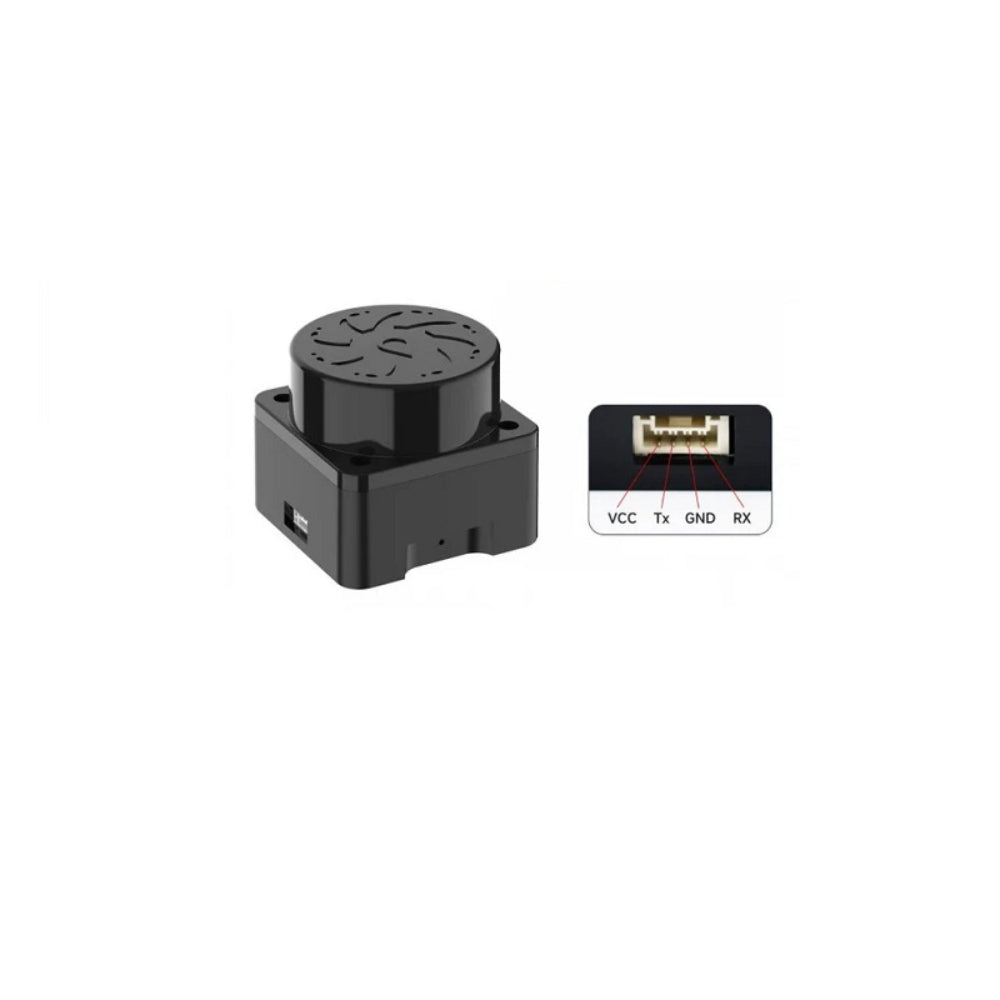
YDLIDAR T-mini Plus — ToF, 360°, 4000 samples/sec
Over YDLIDAR X3, YDLIDAR X4, and camera-only SLAM
LiDAR vs Camera-Only Navigation
Camera-only SLAM (Visual SLAM) requires the scene to have enough visual features to track. A plain white wall, a dark room, or motion blur during a fast turn can all break tracking. LiDAR fires its own laser pulses — it is independent of ambient lighting and doesn't rely on visual features.
LiDAR output:  [(0°, 0.42m), (1°, 0.43m), ... (359°, 0.41m)]
               — precise, lighting-independent, 10× per second

Camera output: image frame → feature extraction → position estimate
               — fails in low light, on featureless walls, with motion blur
Why T-mini Plus Over X3/X4
The 90g weight saving over the X3 reduces motor load on the drive wheels. The 5cm minimum detection distance (vs 12cm) means the robot detects obstacles that are very close — relevant in tight spaces. The X4 was eliminated immediately: discontinued products have no firmware support path.
Why Not Solid-State LiDAR?
Solid-state LiDAR (no moving parts) is more reliable long-term but currently costs $200–500 for robotics-grade units. The T-mini Plus at $71 provides sufficient performance for a prototype. The spinning mechanism is a known wear item — acceptable for R&D.
IMU — ICM-42688-P
Why I upgraded from the hobbyist standard to a current-generation IMU.
ICM-42688-P — 6-axis, 8kHz, low-noise
Over the common MPU-6050
/i/876675/products/2025-11-18T12:55:34.996Z-Screenshot%202025-11-19%20000224.png?1763442960)
Why IMU Noise Matters for Navigation
Between LiDAR scans (every 100ms at 10Hz), the robot's position is estimated using IMU dead-reckoning — integrating acceleration and rotation over time. Noise in the IMU signal accumulates with each integration step. A noisier IMU means the robot thinks it's at position A when it's actually at position B — causing map misalignment and navigation drift.
- Accel noise: 400 µg/√Hz
- Gyro noise: 0.005 °/s/√Hz
- Max sample rate: 1kHz
- Discontinued — clone quality varies
- Accel noise: 70 µg/√Hz (5.7× cleaner)
- Gyro noise: 0.0028 °/s/√Hz (1.8× cleaner)
- Max sample rate: 8kHz
- Active production, current generation
Cost Justification
The ICM-42688-P costs approximately $3–5 vs $1 for an MPU-6050 module. The $2–4 price difference is negligible at prototype scale. The discontinued status of the MPU-6050 is the deciding factor — sourcing discontinued parts from unknown clone manufacturers introduces reliability risk that far outweighs the cost saving.
Cliff Sensor Fusion — IR + ToF
Why I use two sensor types per corner instead of one.
TCRT5000 IR + VL53L0X ToF at each of 4 corners
Fixes the #1 cliff sensor failure mode in the market

The Industry Problem
Every major robot vacuum uses IR-only cliff detection. IR works by emitting infrared light and measuring the reflected signal. Dark surfaces absorb infrared instead of reflecting it — causing the sensor to read "no reflection" and interpret the floor as a cliff. This is not a software bug; it's a physics limitation of the sensing method.
IR sensor logic (industry standard — has failure mode):
emit IR → measure reflected intensity
if intensity < threshold → "cliff detected" → STOP
Problem: dark floor → low intensity → false cliff → robot stops

ToF sensor logic (my addition):
emit laser pulse → measure time-of-flight → calculate distance
if distance > 50mm → "cliff detected" → STOP
No dependency on floor colour — measures actual geometry
Fusion Logic
Both sensors run simultaneously. A cliff is only declared when both sensors agree:
cliff = (IR_reflection < threshold) AND (ToF_distance > 50mm)

Dark floor:  IR says cliff, ToF says floor at 8mm → NOT a cliff
Real cliff:  IR says cliff, ToF says nothing at 200mm+ → IS a cliff
Cost Per Corner
Round Form Factor
Why I chose a circular body despite its corner-cleaning limitations.
Circular chassis — 340mm diameter
Over D-shaped or rectangular form factors
Key Advantage: Zero-Radius Turn
Differential drive on a circular robot allows a zero-radius turn — spinning left wheel forward and right wheel backward rotates the robot around its own centre point. A rectangular robot cannot do this; it must arc outward to turn, which requires more space and more complex path planning.
The Corner Trade-off
A 340mm diameter robot leaves approximately 30mm of uncleaned space in 90° corners. This is a known limitation of every round robot vacuum on the market. The alternative (D-shaped body with a flat front edge) reduces this to ~5mm but requires the navigation software to know the robot's angular orientation at all times — additional software complexity for a first prototype.
- Better corner coverage (~5mm gap)
- Requires orientation-aware navigation
- More complex 3D chassis geometry
- Asymmetric — harder to balance
- Zero-radius turn — fits any space
- Simplest navigation — orientation irrelevant
- Symmetric — easy to balance PCBs and battery
- Industry-proven across millions of units
Anti-Tangle Brushroll Geometry
Addressing the #1 maintenance complaint across all robot vacuums.
Spiral-fin + rubber flap hybrid brushroll
Over standard cylindrical rubber brushroll

Why Standard Brushrolls Tangle
A cylindrical roller provides no directional guidance to hair. Long hairs naturally wrap around the cylinder circumferentially — perpendicular to the direction of intended airflow. Within a few cleaning sessions the roller is completely occluded, motor current spikes (overcurrent protection may trip), and suction efficiency drops by 40–60%.
The Spiral-Fin Solution
Spiral fins run helically along the brushroll length. When a hair contacts the fin, it is guided along the helix toward the end of the roller rather than wrapping around the circumference. At the ends, the accumulated hair can be easily removed without tools — a single pull rather than cutting with scissors.
Standard roller:  hair wraps AROUND → builds up → blocks suction
Spiral fin:       hair slides ALONG → exits at end → easy removal
Rubber Flap Addition
Rubber flaps (running parallel to the roller axis) provide carpet agitation — physically beating carpet fibres to loosen embedded debris before suction picks it up. The hybrid design combines spiral fins for anti-tangle with rubber flaps for cleaning performance.
10,000 Pa Suction Target
Why I chose this specific performance target.
10,000 Pa using off-the-shelf robot vacuum fan module
Market context: budget = 1,000 Pa, flagship = 30,000 Pa
Market Benchmarks
Why Not Higher?
Suction above 10,000 Pa requires custom-designed impeller geometry — a mechanical engineering task outside the scope of this prototype. Roborock and Dreame spare fan modules (available on LCSC/AliExpress for $15–30) achieve 8,000–12,000 Pa and are proven in real-world cleaning. I use one of these off-the-shelf modules rather than designing my own for v1.
Important Caveat
Pascal ratings are measured at stall (outlet blocked). Real cleaning performance also depends on airflow volume (CFM), brushroll agitation, and dustbin sealing. A robot with 10,000 Pa and perfect dustbin sealing will outclean one with 15,000 Pa and a leaky dustbin.
Passive Mop System
Why the mop uses gravity-fed water and manual pad replacement in v1.
Gravity-fed felt wick + Velcro pad + servo lift
Auto-wash deferred to v2
What Auto-Wash Actually Requires
Premium robots auto-wash their mop pads at a base station. This requires: a wash basin, a pump, a heater (to dry the pad — wet pads left overnight grow mould), a dirty water drain circuit, and a separate PCB to control all of this. The base station becomes a second embedded system.
Why Passive for v1
My prototype focuses on navigation, sensing, and custom PCB design. Adding auto-wash would require a fifth PCB, a plumbing circuit, and thermal management — tripling the mechanical complexity for a feature that doesn't affect my primary success criteria (navigation, cleaning performance, sensor accuracy).
- Requires base station PCB
- Pump + heater + drain circuit
- Most failure-prone subsystem in current market
- Zero electronics — no failure modes
- 150ml tank, gravity-fed through felt wick
- Servo lifts pad on carpet, lowers on hard floor
- Focus stays on navigation and PCBs
3D Printed PETG Chassis
Why 3D printing over laser cutting, and why PETG over PLA.
3D printed PETG — manufactured via JLCPCB
Over laser-cut acrylic or plywood
Why Not Laser Cutting?
Laser cutting produces flat 2D parts. A round robot body requires either a polygon approximation (ugly, poor fit to PCBs) or a flat top/bottom with a separate curved sidewall. Complex internal features — PCB mounting standoffs, cable routing channels, brushroll cradle, servo mount — cannot be laser cut.
Why PETG Over PLA?
PLA is the easiest plastic to print but softens at ~60°C. The suction fan motor and BLDC motor drivers generate modest heat. In a sealed chassis on a warm day, internal temperatures can reach 45–55°C — PLA parts near heat sources would deform over time. PETG softens at ~80°C, is tougher, and slightly flexible (less brittle on impact).
Manufacturing via JLCPCB
JLCPCB's 3D printing service accepts STL files and produces PETG parts for $10–30 per piece. Ordering chassis parts in the same cart as PCBs means one shipment, one wait. The only tool required: FreeCAD or Fusion 360 (both free for personal use) to design the STL files.
BLDC Motors + Allegro A89301
Why brushless motors and why this specific driver IC.
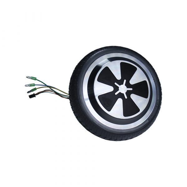
BLDC motors with Hall encoders — driven by Allegro A89301
Over brushed motors and generic H-bridge drivers
Brushed vs Brushless
Brushed motors use physical carbon brushes to commutate current. In a dusty environment (a floor robot), brush wear is accelerated — lifespan drops to 500–1000 hours. BLDC motors are commutated electronically — no physical contact, no wear, lifespan 5–10× longer. BLDC also achieves >85% electrical efficiency vs ~75% for brushed.
Why Allegro A89301 Specifically?
Field-Oriented Control (FOC) — the technique the A89301 uses — delivers 15–20dB lower acoustic noise than basic 6-step commutation. For a cleaning robot used at night or in quiet homes, this is a real user-experience benefit. The wide voltage range (5.5–50V) means it operates correctly across my full battery discharge range (from 12.6V fully charged to ~10.5V before BMS cutoff).
Why One Driver Per Motor?
Some designs use a single multi-channel driver IC. Individual drivers allow independent fault isolation — if one motor driver faults, the others keep running. The robot can limp home on one drive wheel rather than stopping completely.
Power Architecture — Mixed Buck + LDO
Why I use a buck converter for 5V but an LDO for 3.3V.
Independent buck per board — each regulates from raw battery
Clean/dirty domain isolation; MP2307 buck + AMS1117-3.3 LDO per clean board
Why Each Board Has Its Own Buck
The 4-board architecture splits into a clean domain (Main + Sensor) and a dirty domain (Motor Driver + Power). BLDC motor drivers switch at ~20kHz, creating ground bounce that corrupts voltage references. If clean boards took regulated power from the dirty side, that switching noise would reach the RPi5, STM32, IMU, and cliff sensors. Each board instead draws raw battery voltage (11.1–12.6V) and regulates locally — motor noise stays contained in the dirty domain.
Why LDO for 3.3V on Clean Boards?
The 3.3V rail powers the STM32 and sensors — total draw under 500mA. An LDO dissipates (5-3.3) × 0.5 = 0.85W — negligible heat. A buck converter for 3.3V would save 0.85W at the cost of switching noise on a noise-sensitive board. Not worth it.
Each board regulates from raw battery independently:
Battery (12V) → Main Board:         MP2307 buck → 5V → AMS1117 → 3.3V
Battery (12V) → Sensor Board:       MP2307 buck → 3.3V
Battery (12V) → Motor Driver Board: local regulation → motor supply
Battery (12V) → Power Board:        BMS + buck → system rails

Star ground at battery connector — all boards meet here only
ISO1540 I²C isolator on BQ25798→STM32 link (dirty→clean boundary)
Single USB-C EPR Port
The full reasoning behind one port for both charging and debug.
Single USB-C EPR port — 240W charging + USB 2.0 data
With full protection circuit: TVS + ESD + PD controller + 48V→20V buck
Original Approach: XT30 for Charging
XT30 connectors are the standard for robotics bench charging — high current rating (30A), robust, cheap. I initially specified XT30 for charging with a separate USB-C debug port. This was changed because two external ports creates a user-facing risk: plugging a 48V EPR charger into the 5V debug port destroys the STM32 and RPi instantly.
USB-C EPR Technical Reality
USB-C PD 3.1 (Extended Power Range) supports 48V at 5A = 240W. The E-marker chip in the cable verifies it is rated for this voltage. The BQ25798 charge management IC accepts maximum 24V input — so a step-down converter is required between USB-C VBUS and the charge IC.
In the 4-board architecture, the entire charging path lives on the Power board (dirty domain) — never crossing the inter-board harness. Only the low-current USB data lines (D+/D−) travel to the STM32 on the Main board. Battery % and charge state are read by the STM32 over I²C through an ISO1540 isolator at the domain boundary.
Power Board (dirty domain):
USB-C port
     │
     ├─ VBUS (48V) → [TVS diode] → [TPS65987 PD controller]
     │                                       │
     │                              [48V→20V buck] → [BQ25798] → Battery
     │
     └─ D+/D- ──────────────────────────────────────────────────────────→ JST harness → Main Board

BQ25798 I²C → [ISO1540 isolator] → JST harness → STM32 (battery % + charge state)
High-current charging path is fully contained on the Power board.
Protection Layers
- TVS diode on VBUS — clamps voltage spikes above 60V during plug-in transients
- TPS65987 PD controller — negotiates EPR voltage; charging doesn't start without a confirmed PD contract
- 48V→20V buck — steps VBUS down before BQ25798 (which accepts max 24V)
- USBLC6-2SC6 — ESD clamp on D+/D- lines crossing to the Main board
- ISO1540 I²C isolator — electrically isolates BQ25798 I²C from STM32; prevents Power board ground bounce reaching the clean domain
Cable Requirement
Requires a USB-IF certified USB 2.0 EPR cable (~$12). The E-marker chip in the cable is what enables 48V negotiation — a standard USB-C cable will only get 5V from the charger, which is fine for data/debug but won't charge the battery at useful speed. The charger requires USB-C PD 3.1 EPR support (~$30 for a single-port 240W GaN adapter).
3S2P Li-ion Battery Pack
Why 6 cells in this specific configuration.
3S2P 18650 Li-ion — 11.1V nominal, 5200mAh
Targets 60–90 minutes runtime

Configuration Explained
3S = 3 cells in Series → voltages add:   3 × 3.7V = 11.1V nominal
2P = 2 cells in Parallel → capacity adds: 2 × 2600mAh = 5200mAh
Total: 6 cells, 11.1V, 5200mAh, ~57.7Wh

Cell type: Samsung/LG 18650 (cylindrical, 18mm × 65mm)
Why 18650: most energy-dense consumer Li-ion format, widely available
Why 3S (Not 4S or 2S)?
My motors run at 12V nominal. A 3S pack gives 11.1V–12.6V across its discharge range — compatible with 12V-rated motors without a boost converter. A 2S pack (7.4V) would need a boost converter to reach 12V, adding cost and efficiency loss. A 4S pack (14.8V) would need voltage reduction for the motors, also adding complexity.
Runtime Estimate
Total system load: ~20W. At 57.7Wh capacity with 85% system efficiency: 57.7 × 0.85 / 20 ≈ 2.45 hours theoretical. Real-world with BMS cutoff and peak current bursts: 60–90 minutes — sufficient for rooms up to ~1500 sq ft.
4-Layer PCBs (2 of 4 boards)
Why the additional cost of 4-layer boards is justified.
4-layer for Main and Sensor boards — 2-layer for Motor Driver and Power boards
4-layer adds ~$15–20 per board vs 2-layer
What the Extra Layers Buy
A 4-layer board adds a solid copper ground plane (layer 2) and a power plane (layer 3) between the two signal layers. The ground plane does two critical things:
- Provides every signal trace a return path directly beneath it — dramatically reducing loop area and therefore EMI radiation
- Acts as a Faraday shield — high-frequency noise from motor switching is absorbed before it reaches sensitive sensor signals
2-layer board:
  [Signal traces ↑↓]     ← signals and power share the same layers
  [Ground traces ↑↓]     ← noisy return currents mix with signals

4-layer board:
  [Signal layer]          ← clean signals only
  [Ground plane]          ← solid copper, absorbs EMI
  [Power plane]           ← clean supply for all ICs
  [Signal layer]          ← clean signals only
Why 2-Layer for the Power Board?
The Motor Driver and Power boards handle DC voltages and high-current switching — not sensitive signals. The main concern is current-carrying trace width, not signal integrity. 2-layer is sufficient for both and saves ~$15 per board. The architectural boundary between clean (Main + Sensor) and dirty (Motor Driver + Power) domains replaces the need for 4-layer EMI shielding on the dirty boards.
Single Manufacturer — JLCPCB
Why one supplier for PCBs, assembly, and chassis.
JLCPCB for PCB fabrication + SMT assembly + 3D printing
One cart, one shipment, one point of contact
What JLCPCB Handles
Components are sourced from LCSC (JLCPCB's sister company). You specify components by LCSC part number in KiCad — they arrive pre-loaded on the boards. This eliminates manual component sourcing from multiple distributors.
What JLCPCB Does Not Do
Through-hole components — XT30 connectors (internal battery connection), JST headers (board-to-board cables). These must be hand-soldered. For a prototype, this is 10–20 minutes of work per board. All through-hole parts have large pads and are beginner-friendly to solder.
Iteration Economics
PCB fabrication (5× boards, any size <100×100mm): $2–25
SMT assembly (1 board, standard parts): $20–40
Typical full board respin: $30–65 + 10–14 day wait
→ Validate firmware on Nucleo first to avoid this cost